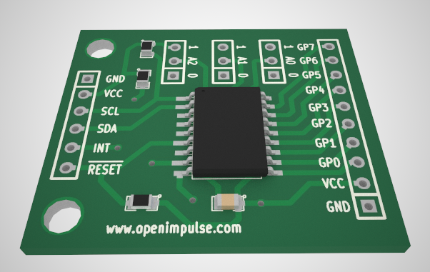
I liked very much the realistic 3D renderings obtained after exporting the board from Eagle to SketchUp, with the EagleUp script. Since the 3D viewer integrated into Kicad is not very realistic and it lacks some features, I searched a way to bring the realistic 3D rendering capability to Kicad and I came up with KicadUp.
KicadUp a script which produces an output compatible with the one generated by the EagleUp script. This way, the board could be imported into SketchUp using the original EagleUp plugin, and you can benefit from the already existing 3D models developed for the Eagle parts.
At this moment the KicadUp script is experimental and uses some features from the development version of Kicad (notably the Kicad Python bindings which offer an easy way to parse the PCB layout files).
Setting up the environment
At this moment, it is a bit cumbersome to use the script, since it only works on Linux, so, you need a Linux box for generating the output. There are two setups which could be used:
- a Linux workstation and a Virtualbox running Windows
- a Windows workstation and a Virtualbox running Ubuntu 12.04 (64 bit)
On Linux, you need to have the following programs installed: ImageMagick, Python, Gerbv
On Windows, you need the following programs:
- ImageMagick (open source, I recommend using the Q8 static binary)
- SketchUp (freeware)
- Maxwell Render for SketchUp (easy to use, the free version is limited to 800×800 px)
- eagleUp_import.rb plugin for SketchUp (it is found in the EagleUp package)
- 3D models (you can get them from the EagleUp warehouse)
The file eagleUp_import.rb should be copied to “C:\Program Files\Google\Google SketchUp 8\Plugins”.
An alternative 3D renderer, which also works on Linux and doesn’t have size limitations is Kerkythea.
Installing KicadUp
Download the KicadUp files from here: kicadup-v0.1.tar.bz2 (compiled under Ubuntu 12.04)
Update: Kicad-Up compiled for Kicad 2013-03-31_BZR4008 under Ubuntu 13.04 64 bit available: kicadup-v0.2.tar.bz2
Unpack the files on you Linux box and type ./kicad_up.py -h in the directory where you unpacked the files. This command should print the help.
If you use a different version of Kicad, try to follow these steps (the example is for Kicad 2013-03-31_BZR4008):
- build Kicad with scripting support by running “cmake -DKICAD_SCRIPTING=ON -DKICAD_SCRIPTING_MODULES=ON” in the Kicad source folder
- delete the file pcbnew.pyc from the kicad_up folder (this will be automatically generated by Python at the first run)
- copy stable_2013-03-31_BZR4008/pcbnew/pcbnew.py to the kicad_up folder and overwrite the current pcbnew.py
- copy stable_2013-03-31_BZR4008/pcbnew/_pcbnew.so to the kicad_up folder and overwrite the current _pcbnew.so
Using KicadUp
In order to use KicadUp for a given project, you need to plot the Gerber files with “Exclude PCB edge layer from other layers” option unchecked. This is necessary because the PCB layout images are generated from the Gerber files.
Run the KicadUp script on the Linux box and then import the generated files in SketchUp, as you would do with the files generated by the EagleUp script.
Usage example: ./kicad_up.py project_name_here path_to_project_folder_here
Limitations
The script only works on Linux because it uses Gerbv to generate the PCB layout images, and it seems that the Windows version of Gerbv can’t be used from the command line.
At this moment, KicadUp only works with rectangular boards.



Hi,
This plugin is really a must but does not work on Windows as is a major blocking point and also does not work with round border.
Have you planned to update it like ruby script/plugin for Sketchup in order to be multi plateform ?
Like for example the very good kicad.rb plugin for Sketchup to import Kicad .brd in sketchup but it lacks possibility to import trace and components like in EagleUp/KicadUp
Best Regards
Benjamin
Actually I am planning to make it work on Windows too .. all what I need is to find a method for converting the Gerber files to images. This is used to model the traces, the soldermask and the silkscreen.
I’m thinking to modify the Windows version of the Gerbv tool to make it work from the command line too.
Cool work.
Doesn’t work with the current builds though, getting the following;
Traceback (most recent call last):
File “./kicad_up.py”, line 9, in
from pcbnew import *
File “pcbnew.py”, line 2493, in
class BOARD(BOARD_ITEM):
File “pcbnew.py”, line 2505, in BOARD
__swig_setmethods__["m_NbNodes"] = _pcbnew.BOARD_m_NbNodes_set
AttributeError: ‘module’ object has no attribute ‘BOARD_m_NbNodes_set’
…I’m guessing some details of the interface have been changed, will try and take a look when/if I get time – took a whole evening to get kicad built with scripting support
DAVE
I’ll check it with the current build to see if there are any issues.
Did you update both the pcbnew.py script and the _pcbnew.so dynamic library with the ones from the new build ?
The problem seems to arise because of the fact that you copied only _pcbnew.so to the kicad_up folder. You also need to copy pcbnew.py from the current Kicad build to the Kicad-Up folder and to delete pcbnew.pyc (which is automatically generated by Python at the first run).
I’ve just tested the script with with the latest stable version (Kicad 2013-03-31_BZR4008), and it seems to be ok.
I’ve also published the new build and I’ve updated the documentation.
this should soon become thing of past because there is always plenty of development in KiCad camp:
http://www.varesano.net/blog/fabio/kicad-getting-awesome-3d-rendering
Yes, I included the_pcbnew.so from the new build, with no change. It does look like something has changed…..
ImportError: /home/lmn/kicad-dev/kicad-up/_pcbnew.so: wrong ELF class: ELFCLASS64
on Debian 32bit
The _pcbnew.so bundled with KicadUp is built for 64 bit linux. It seems that you are using a 32 bit linux version, so you should recompile Kicad for your system.
thank You
Hi to all,
I’ve managed to include the patch that Thomas Spindler did to add kicad 3D realistic rendering of 3D pcb objects and board with copper layers and drill to the 3D viewer of kicad…
please visit
https://sourceforge.net/projects/kicad-3d/
to find win binaries and source code to be built in linux and osx
demo board and utilities are included
Maurice