
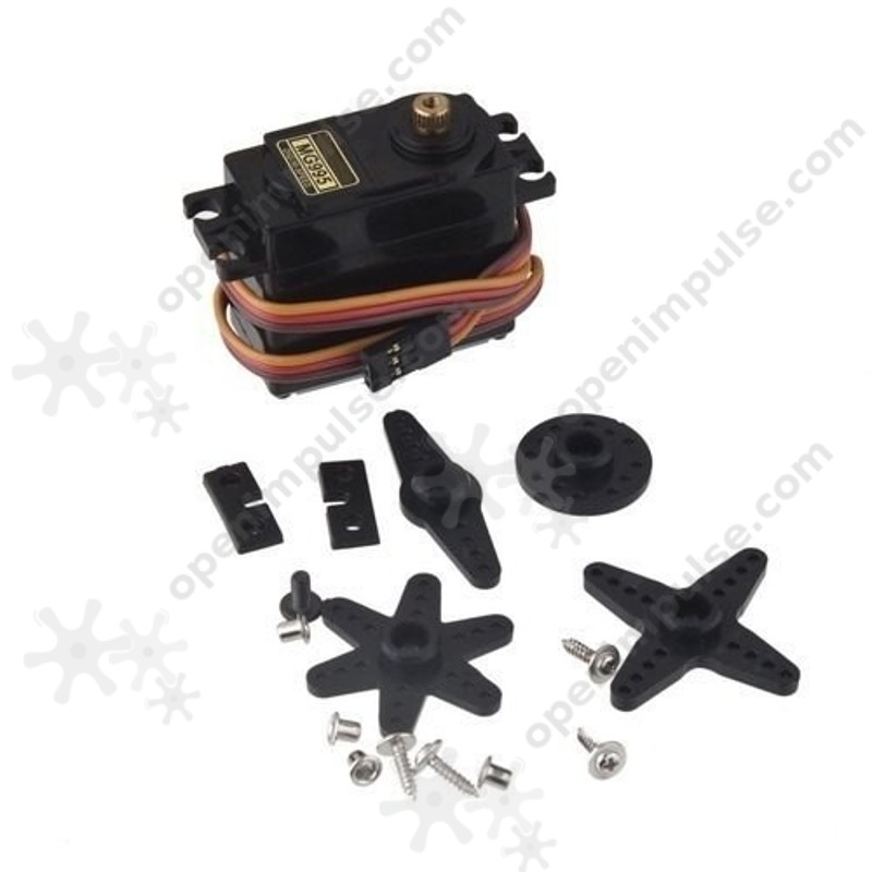
MG995 servomotor that can be used for high precision.
SKU: OTH17392171945,WUM39886608783 |
OverviewThis servomotors are used in very varied applications where precision is required. This type of servomotor is a very common one, stronger than the S3003, and you can use it to build your own 3D printer or CNC or in telehandled machines to move the front wheels into curves. This actuators consist of a DC motor, a motor-driven potentiometer measuring the angle at which it rotates, a circuit that compares the signal from the potentiometer to the user input, and a gear mechanism that reduces the speed engine, but increases its torque. Using the information in the datasheet, you can calculate why the signal is needed to rotate the engine to a certain number of degrees. An advantage to the stepper motors is that when they are idle, the servo motors do not consume current, but they can not keep the shaft locked. Specification
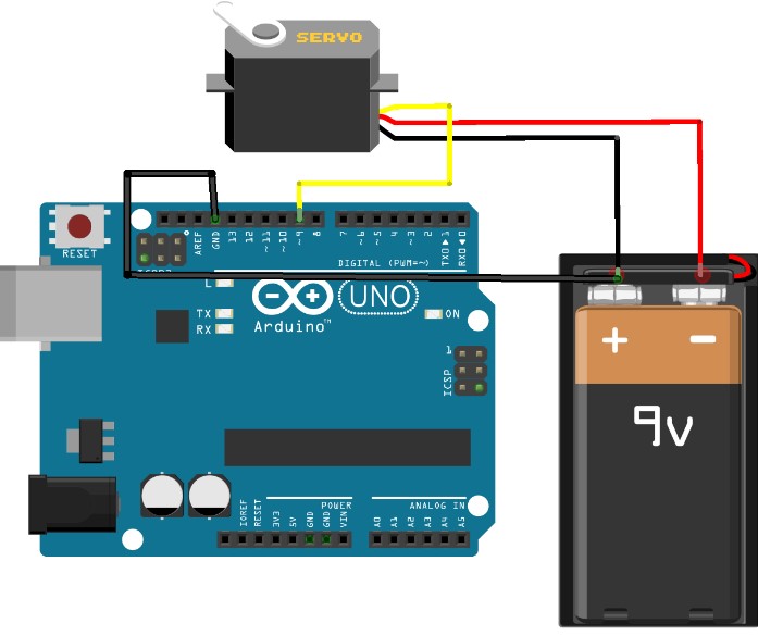
Use with ArduinoIf the actuator is commanded to position itself at a certain angle, but due to inertia it will rotate slightly more than desired, the control circuit inside the actuator will sense this problem by means of a potentiometer that measures its position and will quickly correct the error. Also, if we try to change (mechanically) the position to which the servomotor has been set, it will resist resistance. These qualities make ideal servo motors for applications where accurate control is required, such as robotic arms. There are three wires for connection: GND, 5V and one wire for command, which we will connect to a PWM pin on the Arduino pad. As with DC motors, it is not recommended to power directly from the Arduino plate. We will use a 9 V battery. Attention, the negative battery terminal must be connected to the GND of the card. Most of the times, the actuator terminals will follow the code in the figure below (yellow - control, black - GND, red - power supply). To check this and see other parameters for your engine, you can see the data sheet provided by the manufacturer. Here you will also find other information, such as rotation speed, torque and recommended power supply.
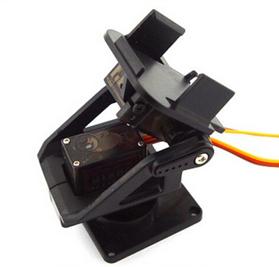
For code 15.0, see the book "Introduction to Arduino" https://www.optimusdigital.ro/altele/1676-carte-introducere-in-arduino.html Perhaps the greatest advantage offered by Arduino is its open-source community, with numerous examples and libraries. We use the Servo.h library to control the actuator. This allows us to declare up to 8 Servo objects and use functions related to these objects such as attach (pin) to indicate to the object what pin communicates or writes (position) to directly control the position of the servo (on the pin indicated by the attach () method will generate a PWM that controls the servomotor). So, an object in programming languages is an instance (variable of a certain type) that can have specific data and functions (methods). The previous program controls the actuator to achieve movements from 0 to 180 degrees in both directions. Using a 2-axis mechanical kit (see the illustration below) and two servomotors, you could easily build a robotic arm. You can use a joystick to control it.
Two-axis positioning system Downloads |
Open Impulse
Arduino, Electronic modules and Robotics

")
")


")