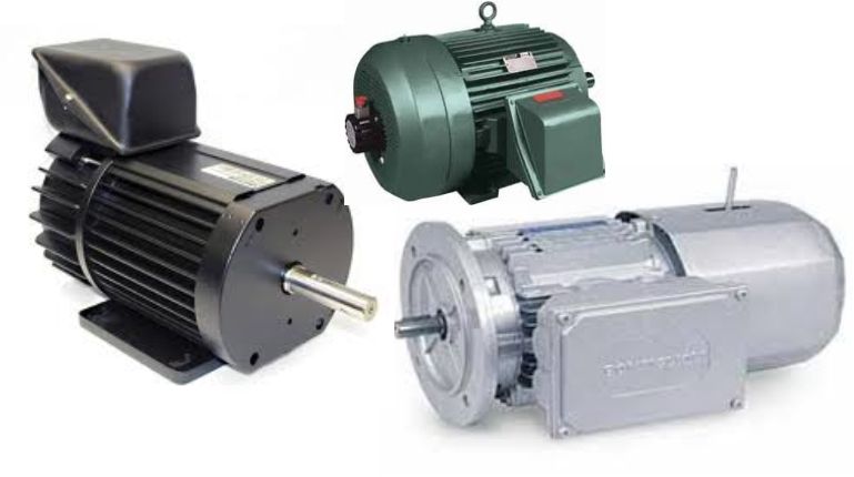
 The DC motor is an electro-mechanical energy converter which converts electrical energy received from a DC source into mechanical energy that gives on to the shaft of a driven mechanism.
By the way the excitation is done, engines are classified in:
- Motor with shunt excitation (parallel) – the stator winding and the rotor winding are connected in parallel to the same voltage source;
- Motor with series excitation – the stator winding and the rotor winding are connected in series;
- Motor with mixed excitation (compund) – stator armature presents two windings: one connected to the parallel rotor winding and other connected in series with it.
Constructive elements
Constructive, the DC motor is composed of an inductor and a induced, separated by an air gap called the air-gap. The inductor is fixed, constituting the machine stator and the armature is movable, representing the rotor machine.
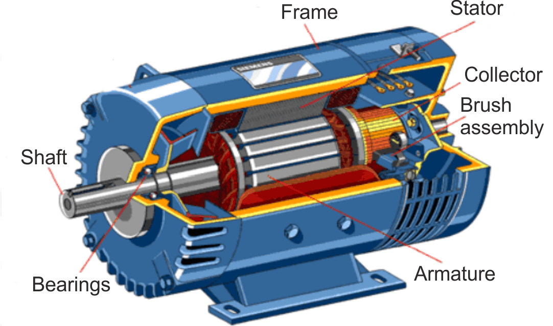 The inductor is the component of the machine that produces the magnetic flux inductor. Is composed of: casing, main poles (excitation), auxiliary poles (switching) and clamping parts.
Main poles are formed from a ferromagnetic core. On the polar core, excitation coils are mounted made of insulated copper conductors with circular section for low powered machines and rectangular for high power machines.
Auxiliary poles consist of a core of solid iron (sometimes of laminations). The pole auxiliary coil is usually made from copper bar bent panels. Auxiliary poles are placed in the geometric neutral axis of the machine, midway between the main poles.
At the polar core outskirt, to the main air-gap a number of notches are practiced on which you place a special winding, called winding compensation.
The armature is composed of a ferromagnetic core, shaft, induced winding and collector. The ferromagnetic core is made of laminations of electrical steel 0.5 mm thick, insulated between each other in order to reduce eddy currents. Most commonly, the armature presents open slots to allow the introduction of pre-insulated coils.
The induced winding is made of copper conductor. The winding portion between two neighboring collector blades is called section. The ends of the section are connected to the collector blades.
The collector is a rotary mechanical rectifier, integral woth the armature of the machine and is made up of a number of blades (isolated from each other) to the trapezoidal shape made of the copper or copper alloy and silver.
Brushes step on the commutator blades, linking the armature circuit which is mobile and the external circuit is fixed.
The DC motor operation is defined by the starting, operation, speed control and braking characteristics.
Starting methods
In practice the following methods to start the DC motors are used:
- Direct connection to the network;
- Start with a starting rheostat;
- Start with low voltage.
There are situations where it is possible to apply the latest methods combined.
Speed control
Assuming that the resistant torque value at the motor shaft is kept constant whe have the following possibilities of controling the speed:
- By varying the excitation flux;
- By varying armature voltage applied to the terminals (the voltage remains constant);
- By varying the power supply voltage.
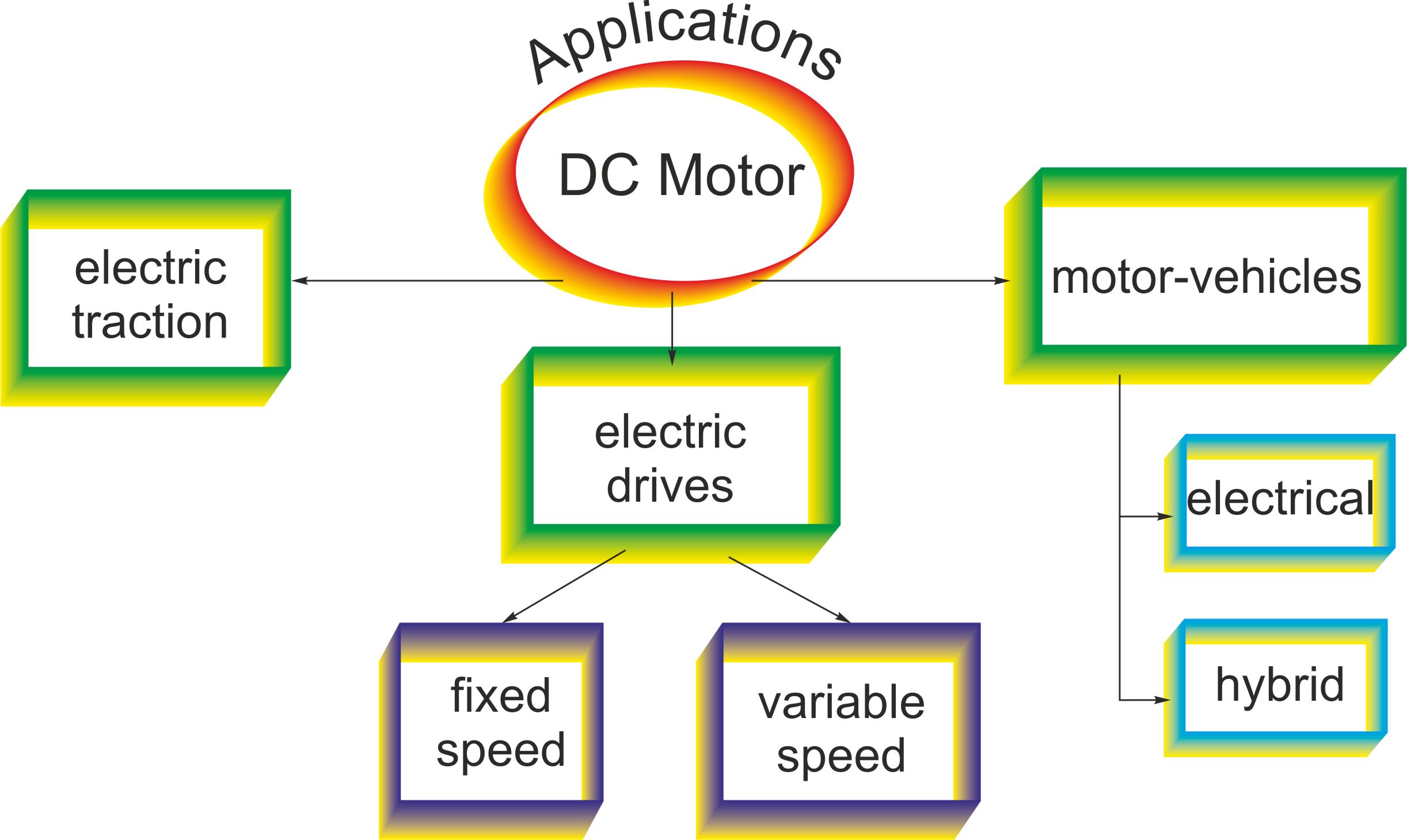
Applications